CATIA V5 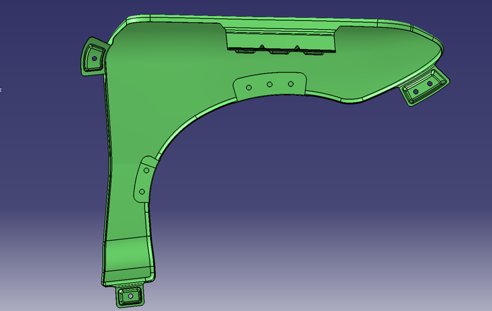
Class-A Surface Panel
Outer body panel built as trimmed surfaces with mounting bosses and cutouts.
Demonstration corpus
Every sample below is a real modelling session — not a screenshot library. Clicks, the named UI element under each click, the alternatives that were available and rejected, window geometry, narration and per-step file state, all on one clock.
Production capacity
Demonstration data is bounded by how many experts you can put in front of the software, not by how much compute you have. This is the network that records it — practising engineers across mechanical, electrical, embedded and digital domains, already delivering technical programmes every month.
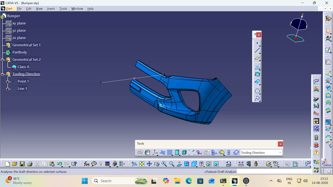 ▶
▶ A STEP file arrives with no history: extract the boundary, build reference geometry, run a draft analysis with the pull direction set, then offset the surface and resolve the multi-result.

Outer body panel built as trimmed surfaces with mounting bosses and cutouts.
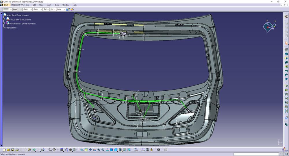
Electrical harness routed through a liftgate assembly against the trimmed body.
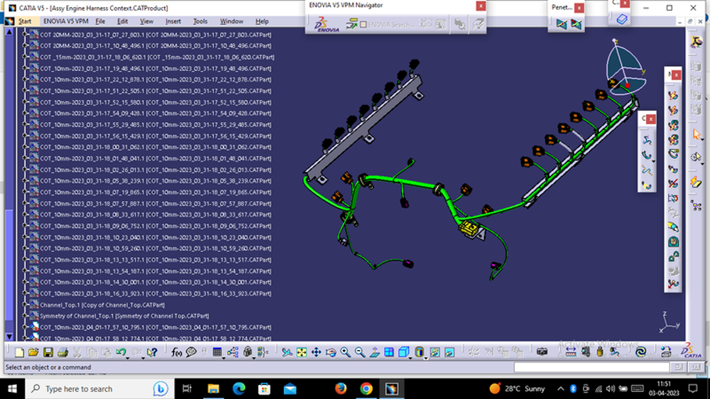
Connector and branch routing driven from the VPM navigator over a long product tree.
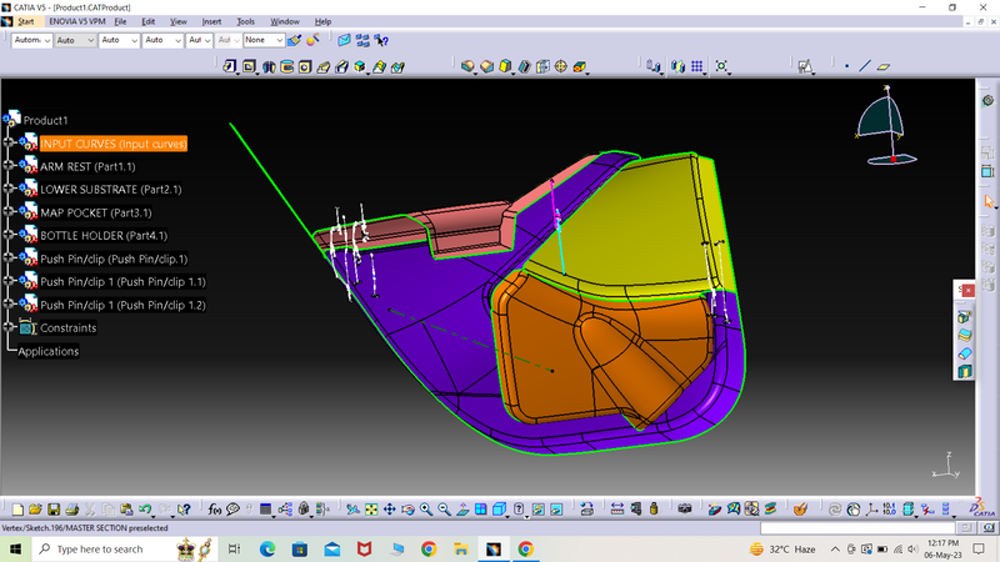
Arm rest, substrate, map pocket and push-pin locators in a single product structure.
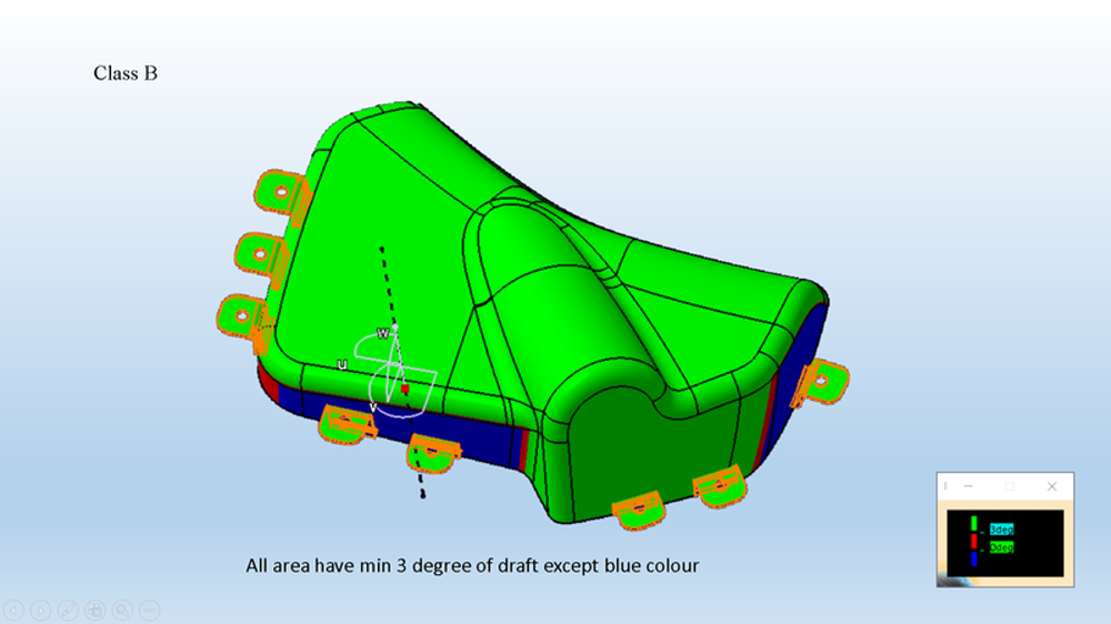
Draft check across a moulded part — every face above three degrees except the blue.

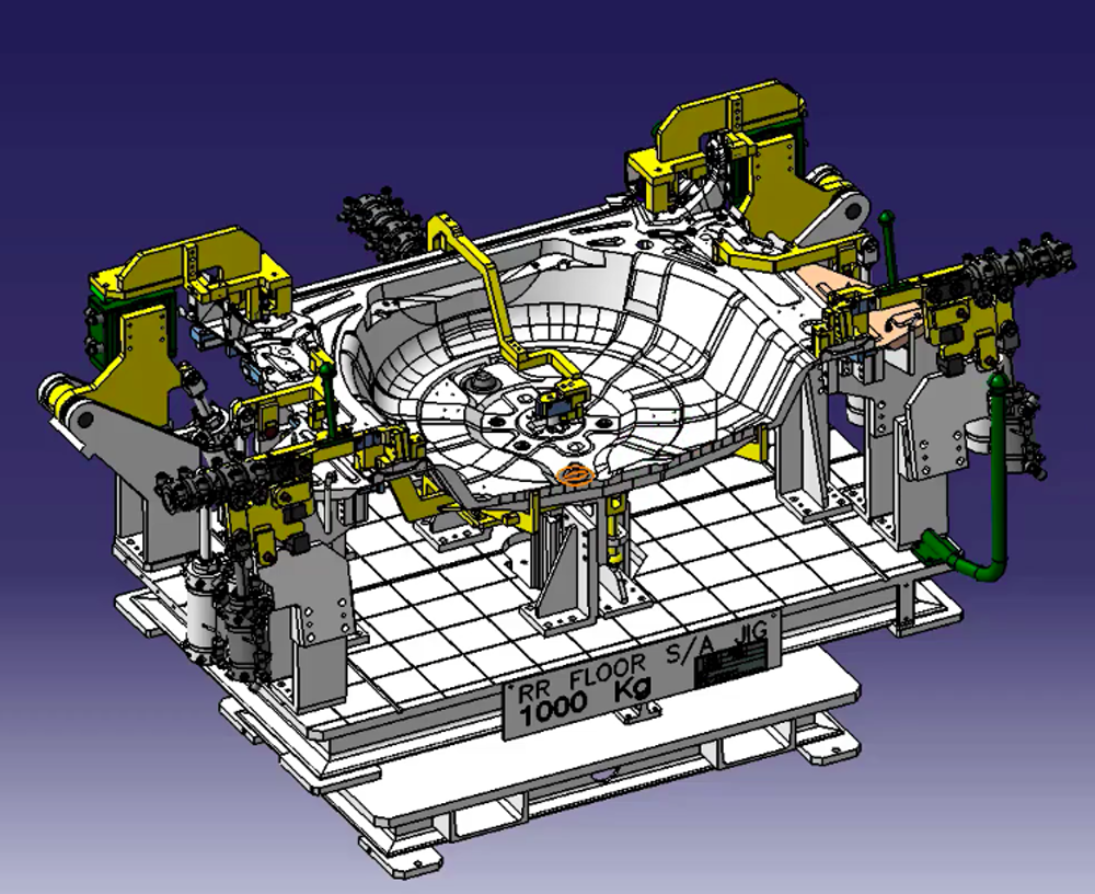
Clamps, rests and locators positioned on a base plate around a wheel house panel.
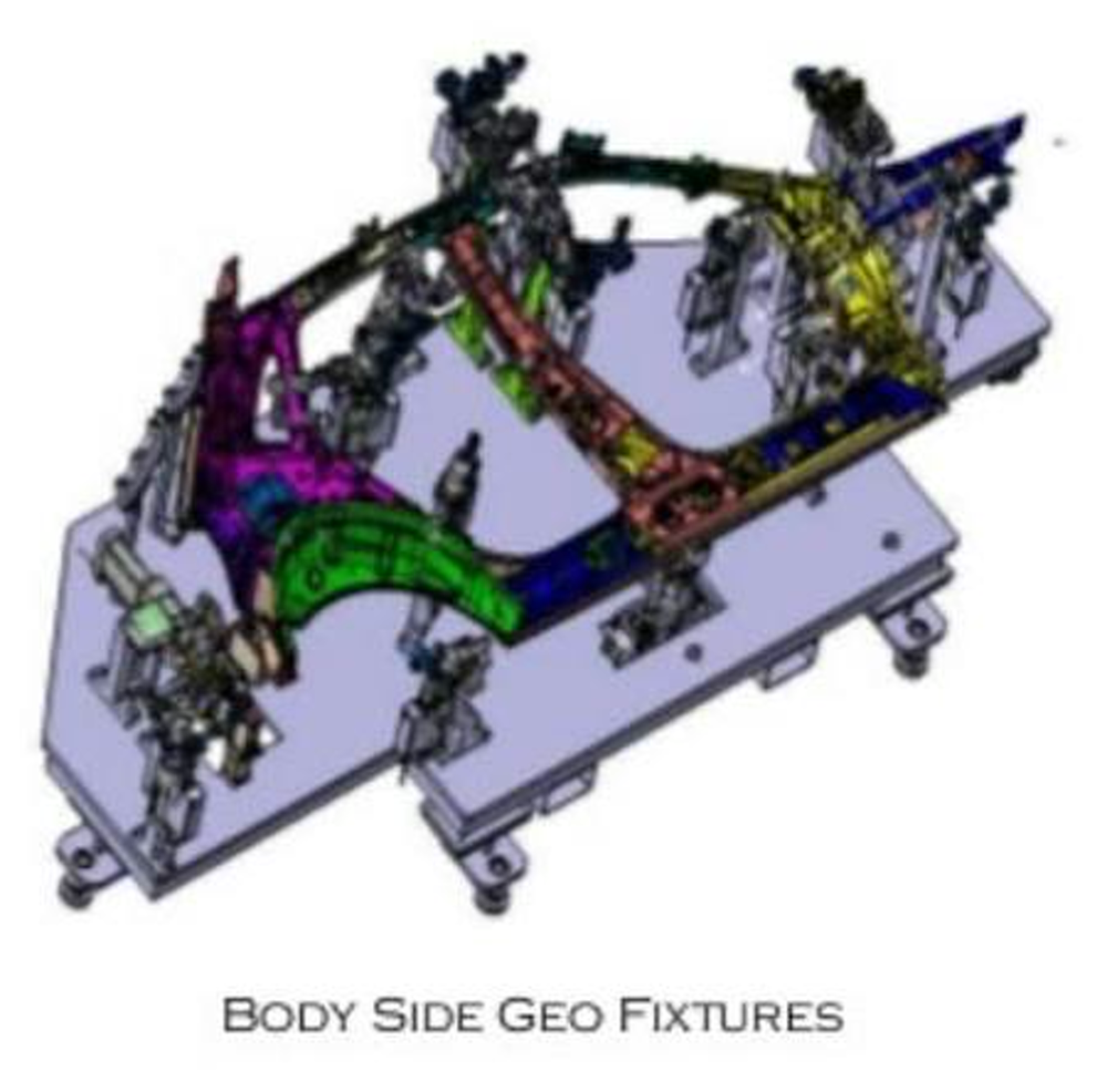
Full body-side fixture layout with colour-coded sub-assemblies on a welded frame.
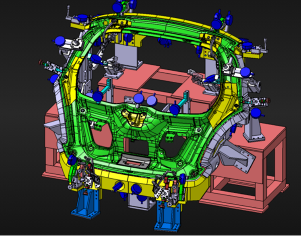
Clamp and pin scheme on a body frame, laid out for weld access and datum control.
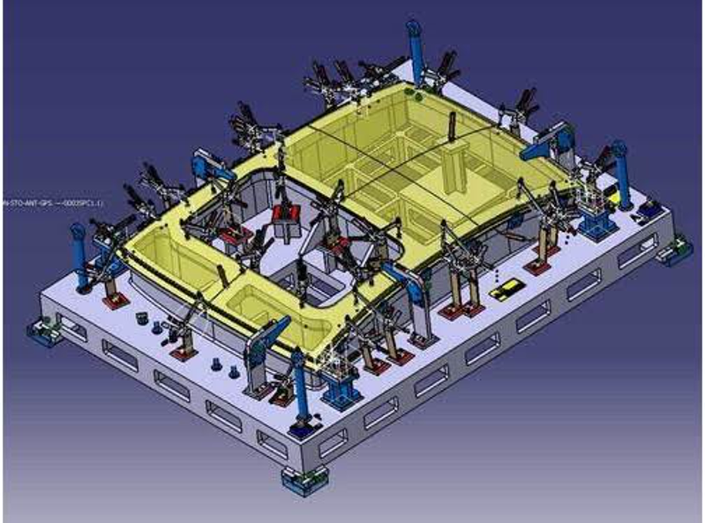
Support pads and toggle clamps set out on a gridded base for a floor panel.

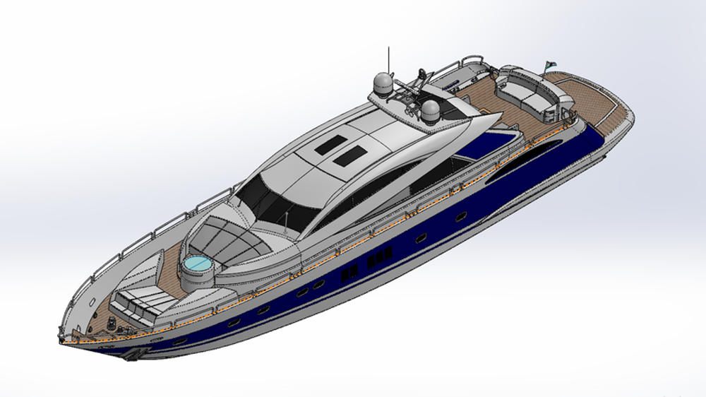
Hull, deck and superstructure surfaces resolved into one assembly.
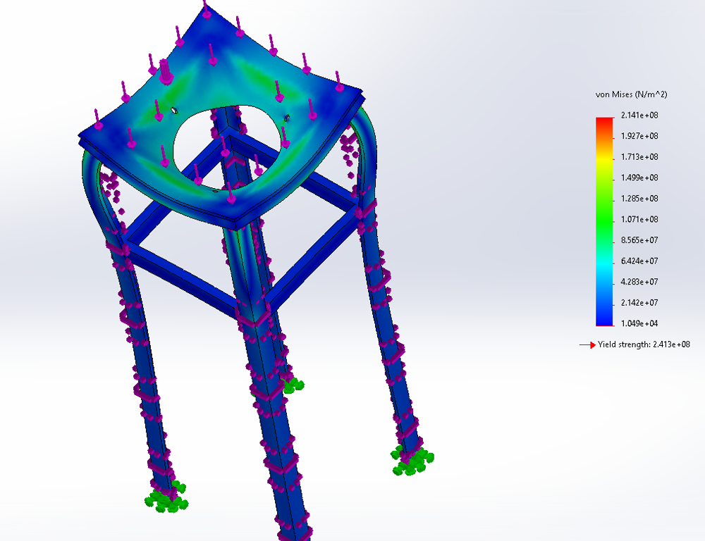
Von Mises result on a welded frame with restraints and loads against yield.
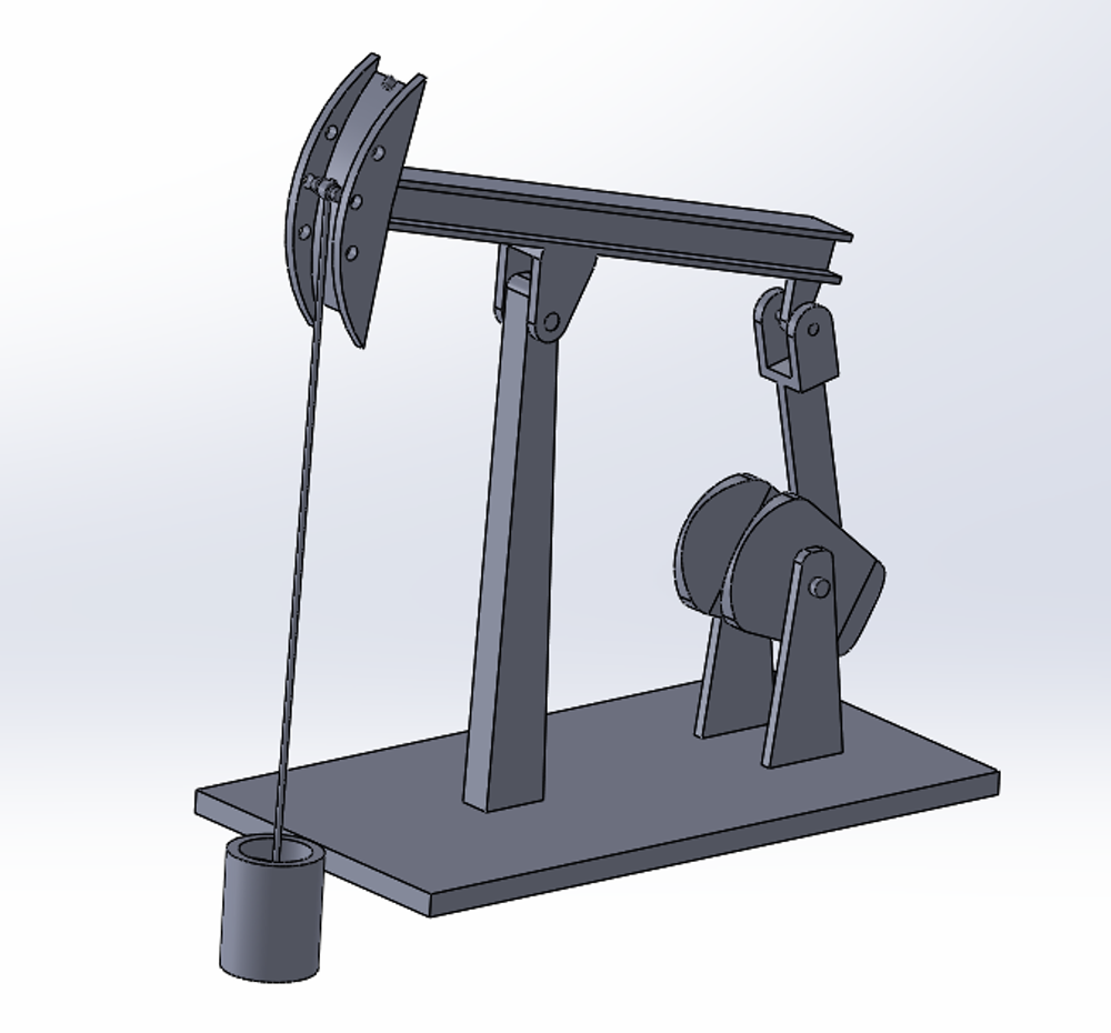
Beam pump linkage — crank, walking beam and counterweight in a mated assembly.

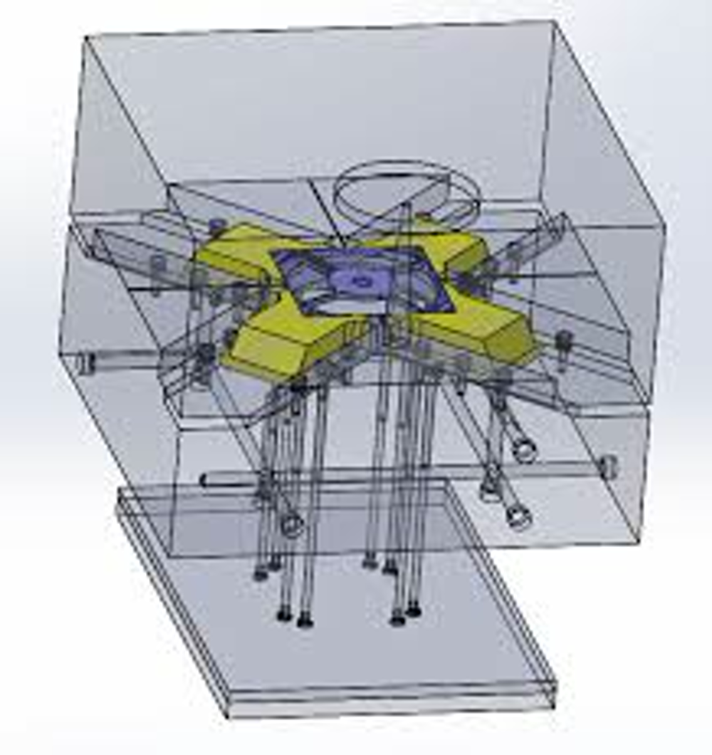
Transparent tooling block showing the cavity, ejector pins and cooling layout.
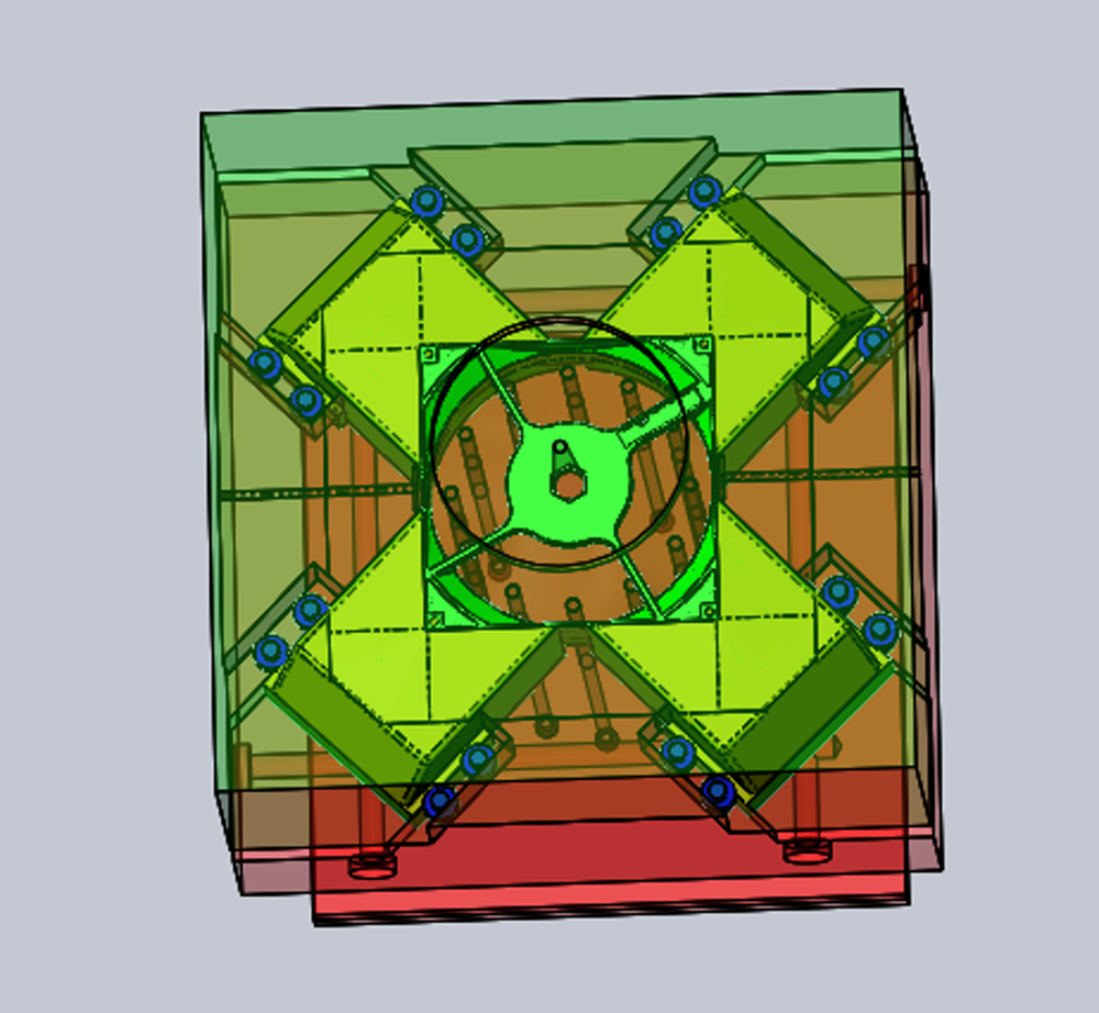
Parting surface with the core and cavity halves separated from the part.
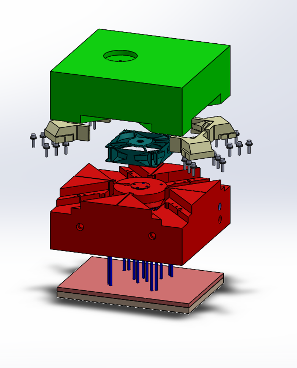
Plates, inserts and ejector assembly exploded through the stack.

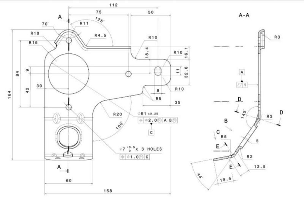
Developed blank dimensioned with bend lines, radii and a hole schedule.
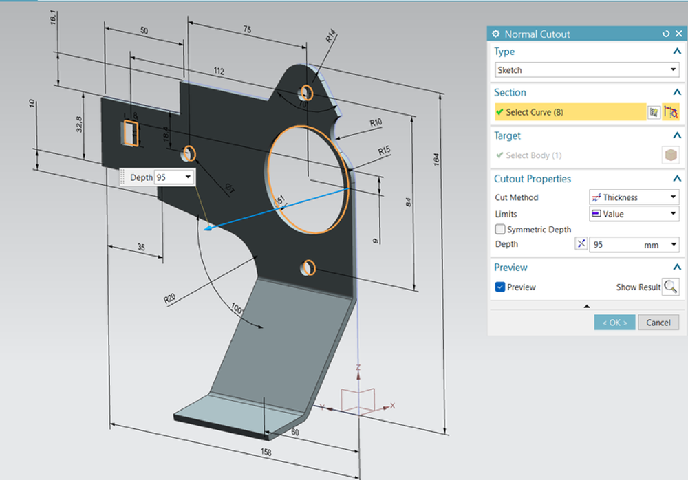
Normal cutout applied through a formed wall, cut depth driven by thickness.
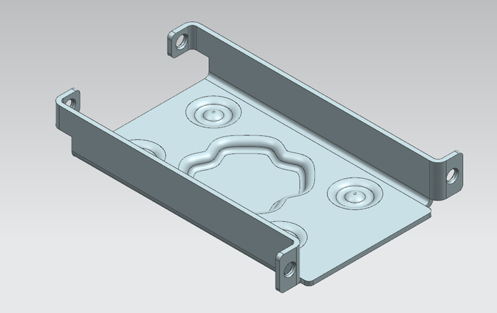
Formed tray with embossed reinforcements and mounting tabs.

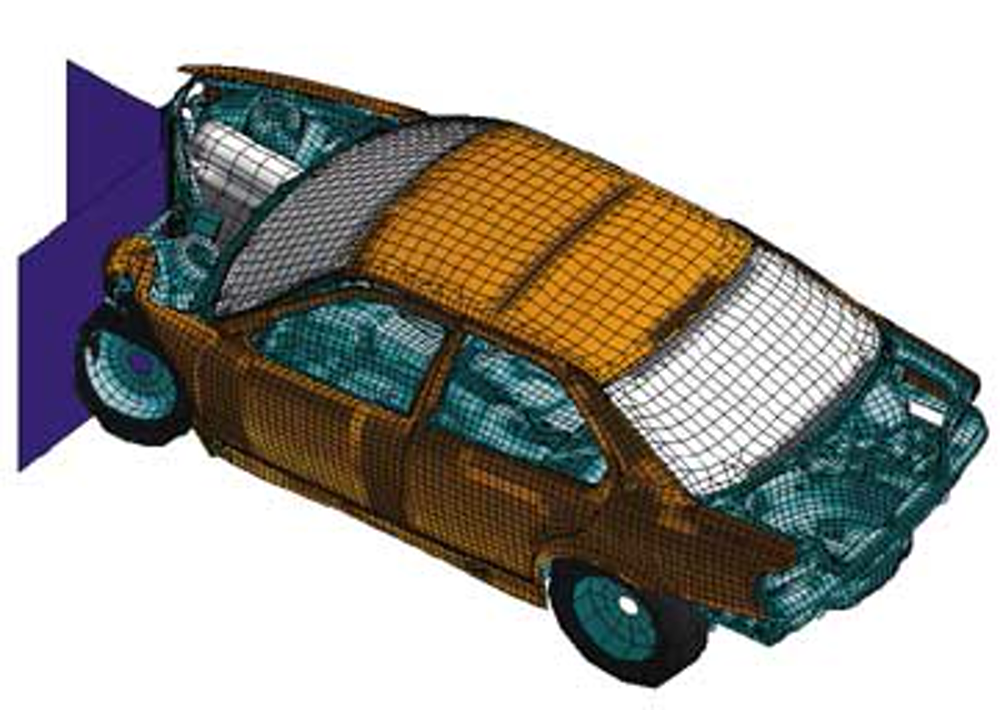
Body-in-white meshed end to end, components separated by property.
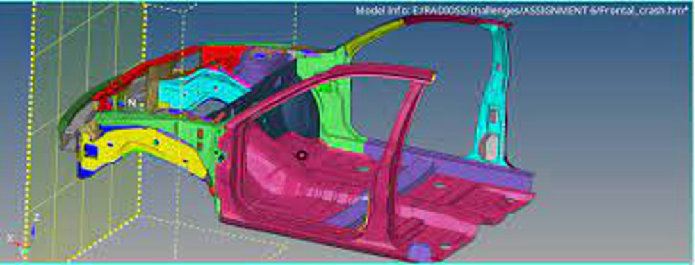
Body side and closures meshed for a frontal impact run, colour-coded by part.
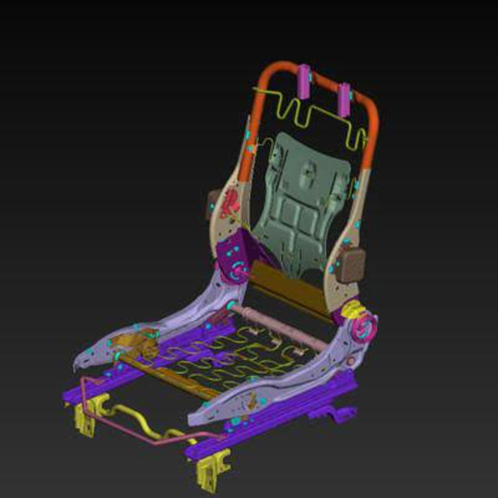
Seat structure, rails and recliner components meshed and grouped.
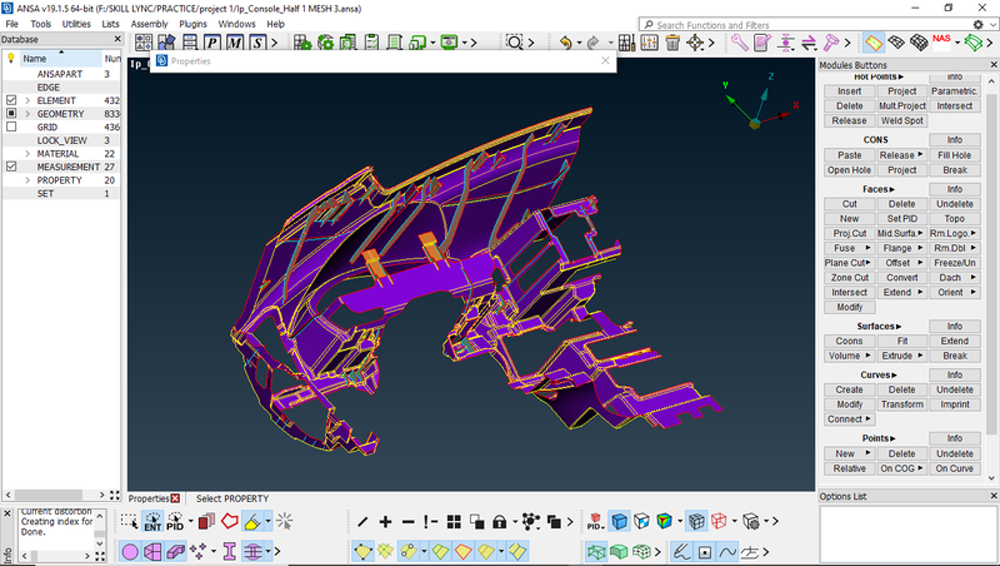
IP substrate cleaned and meshed with feature lines preserved.
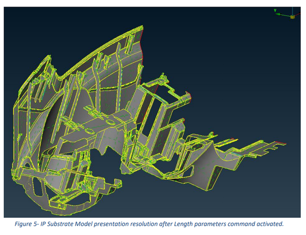
Presentation resolution after length parameters were applied to the model.
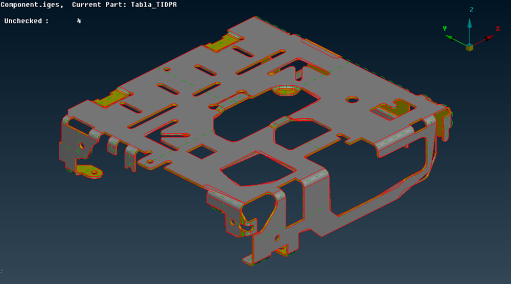
Sheet bracket with edges and holes flagged for mesh controls.
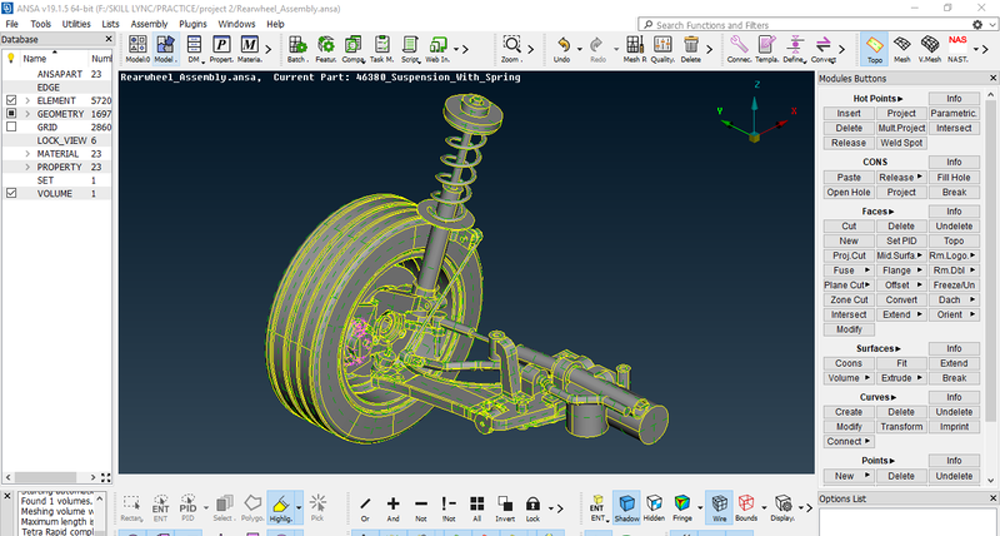
Wheel, knuckle and spring assembly prepared for a durability run.

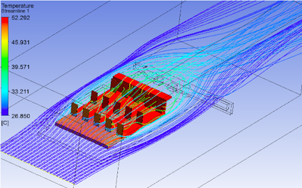
Temperature-coloured streamlines through a populated board in an enclosure.
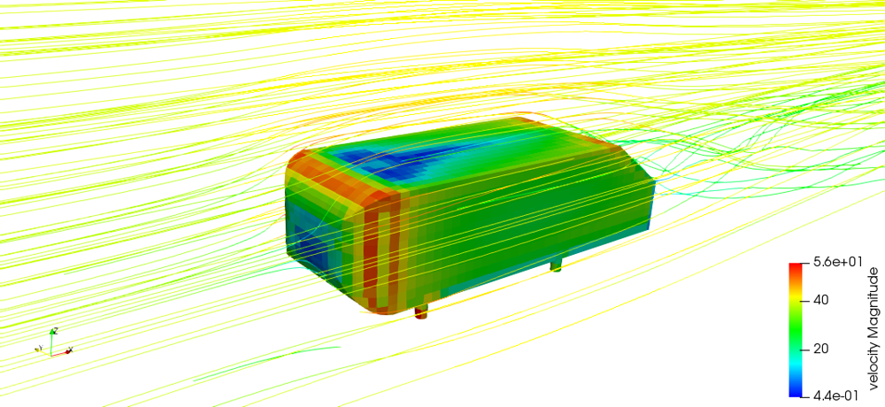
Velocity streamlines and surface field around a blunt body.

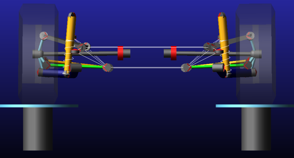
Double wishbone with spring-damper units run through travel on test pads.
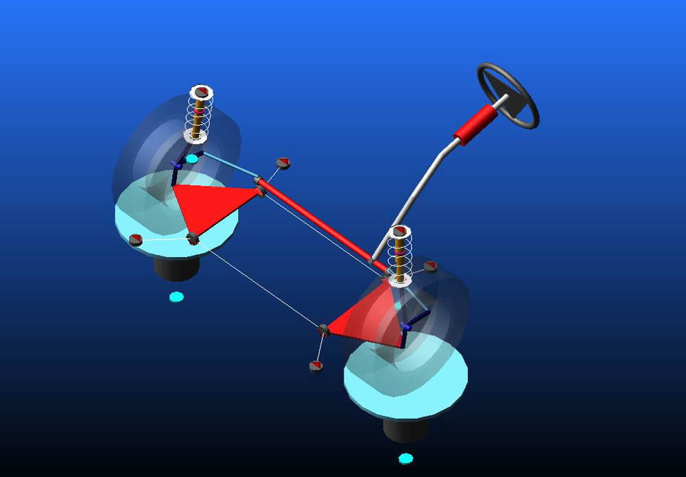
Wheel, hub and link geometry with joints defined for a kinematic solve.

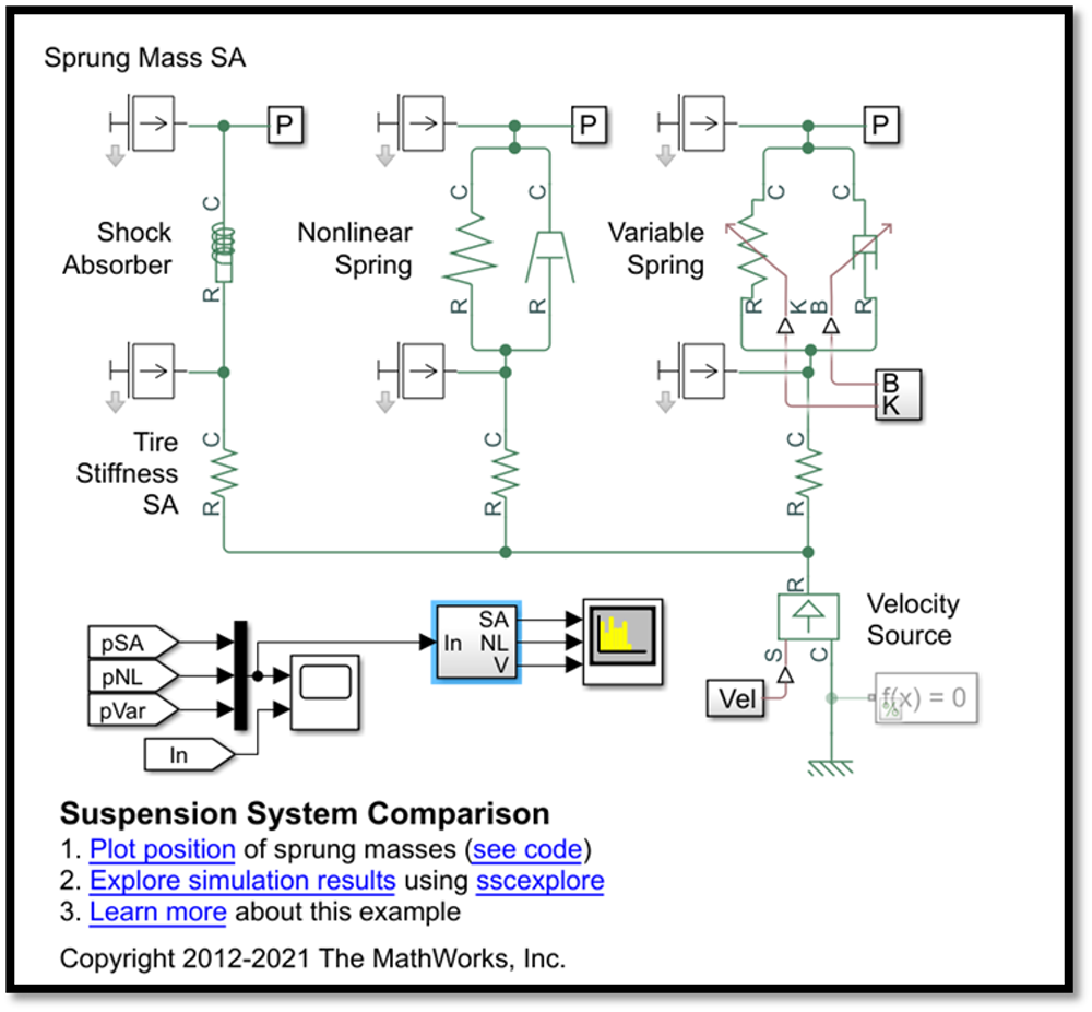
Sprung mass model with shock absorber, nonlinear and variable spring branches.
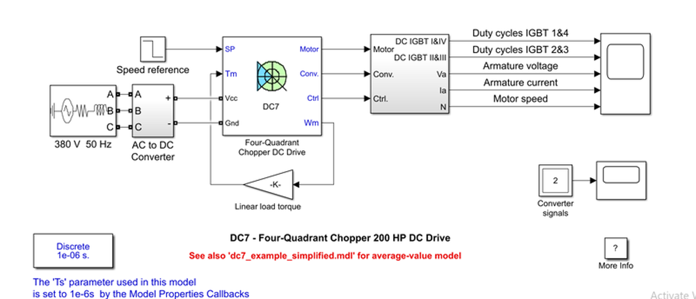
200 HP chopper drive from a three-phase supply with duty-cycle control.
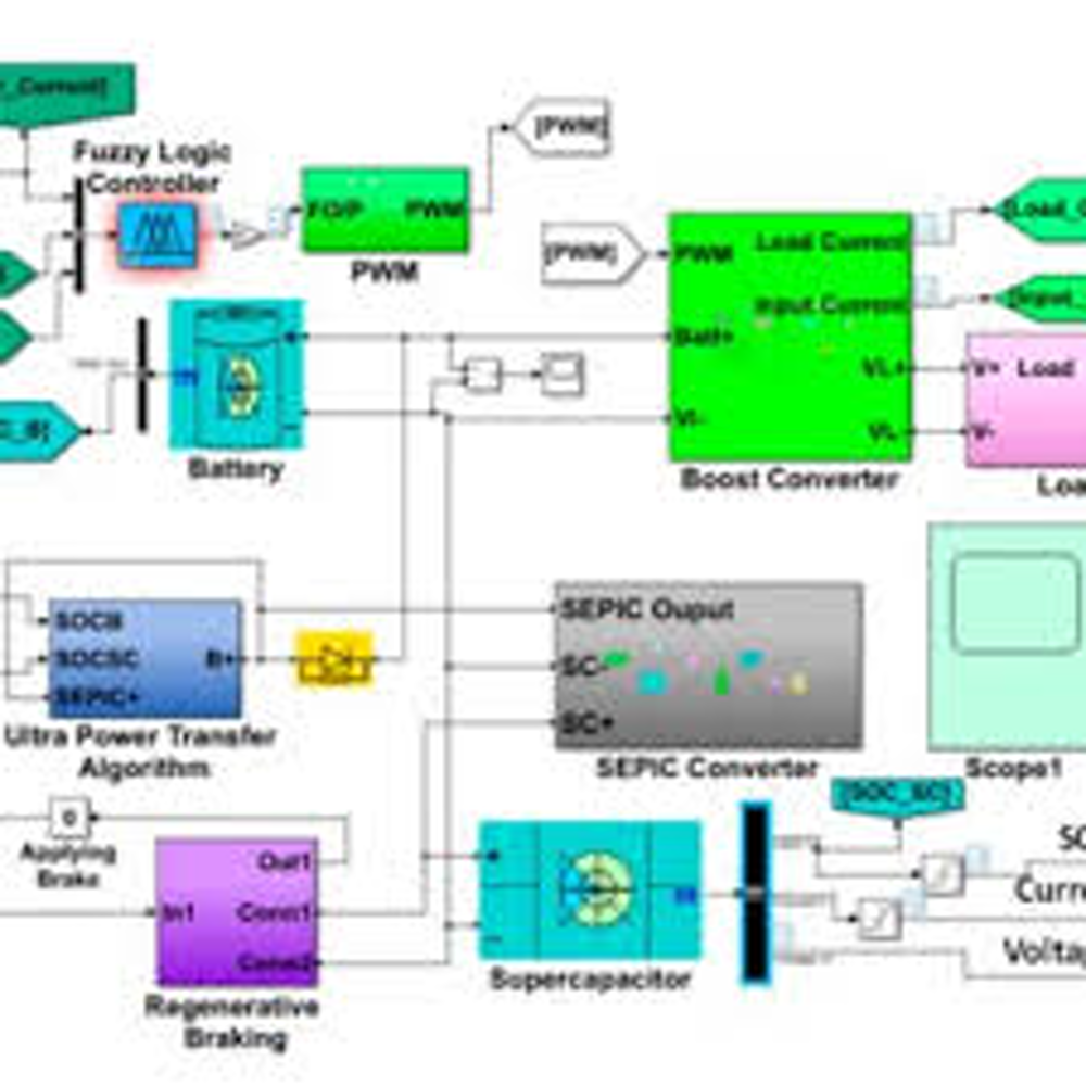
Fuzzy logic controller driving a SEPIC stage with regenerative braking.
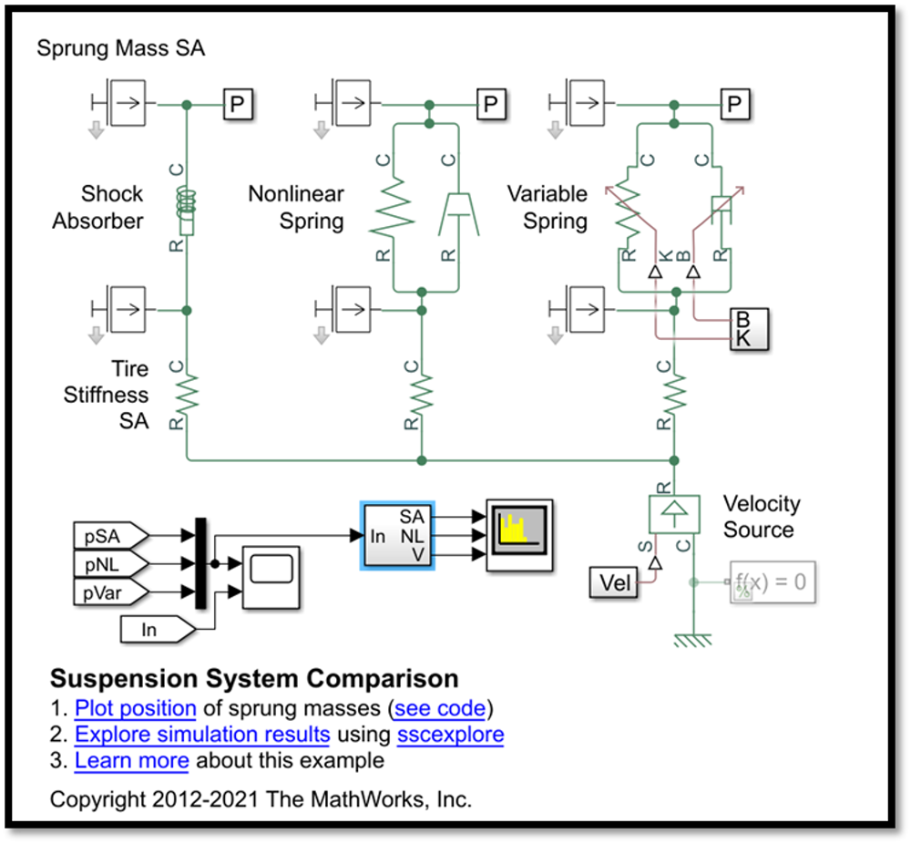
Tyre stiffness and velocity source wired into a comparison harness.

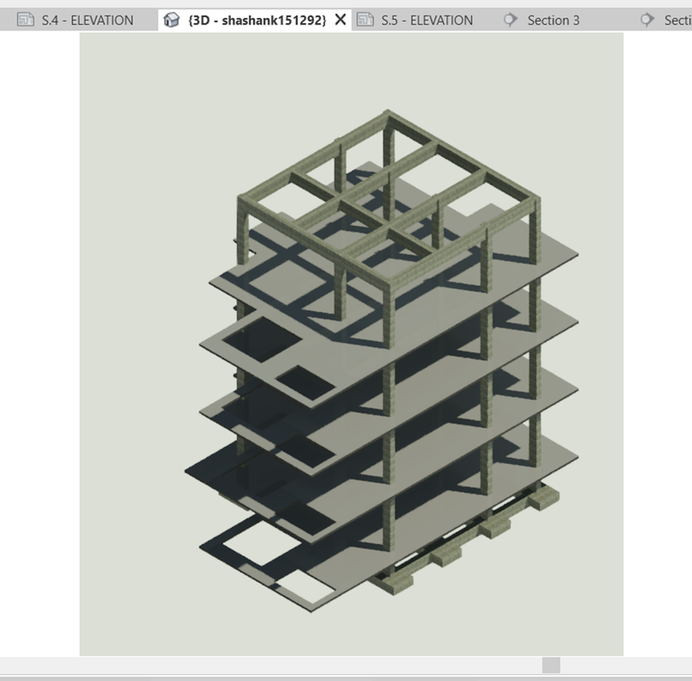
Framing and slabs separated level by level through the building.
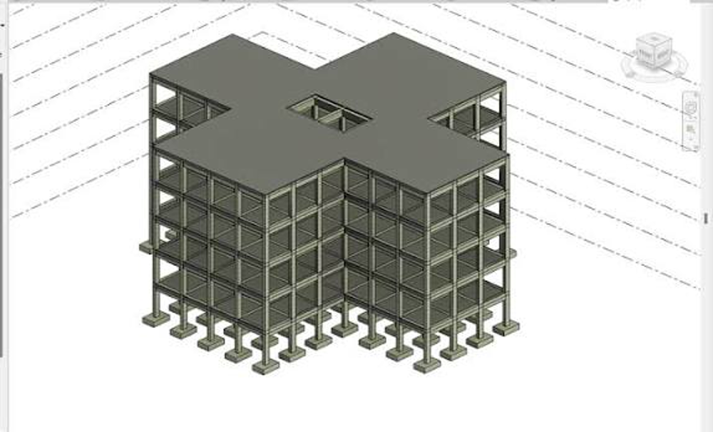
Columns, beams and cores modelled across a cruciform footprint.
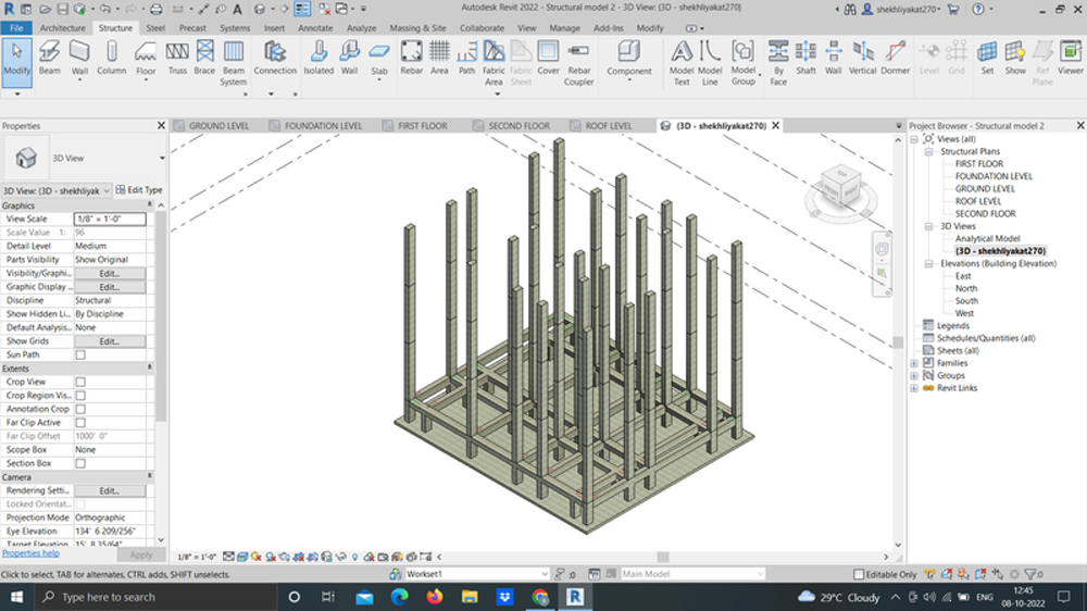
Column set-out driven from grids, with the structural browser open.

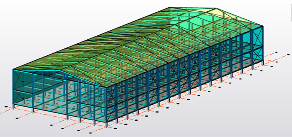
Steel portal frames, purlins and bracing detailed as a connected model.
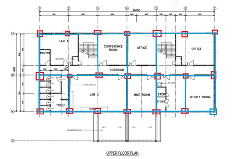
Room layout and grid dimensions issued as a floor plan drawing.
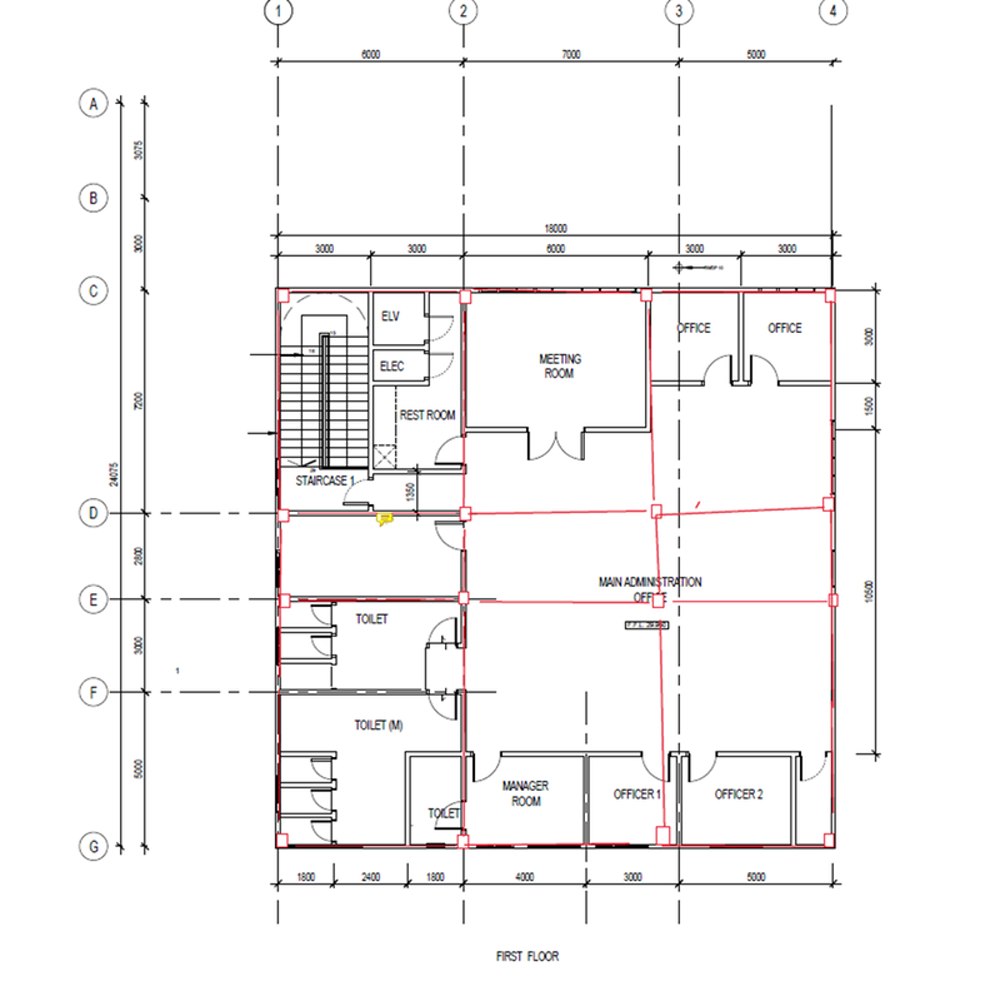
Partition set-out and service rooms dimensioned for issue.

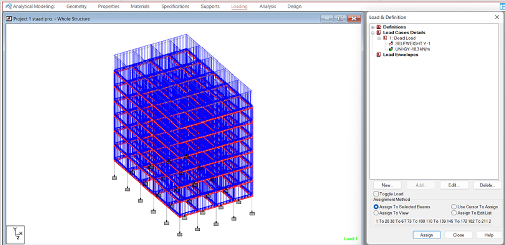
Multi-storey frame with load cases assigned and envelopes defined.
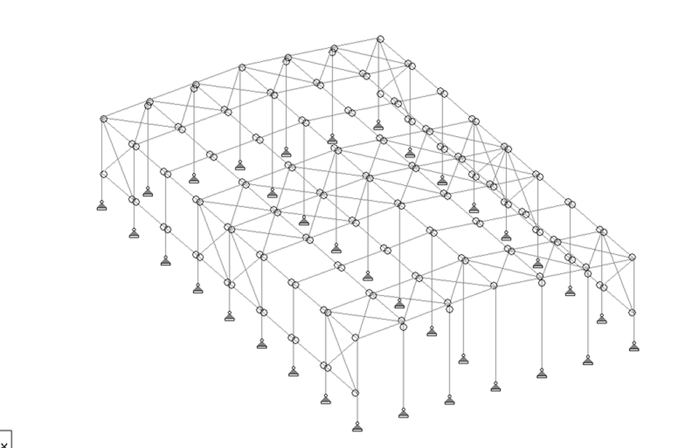
Roof truss modelled with supports and member releases set.
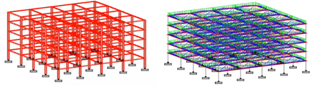
Bare frame beside the analysed model with member forces displayed.
Who we work with
Engineering software vendors on one side, the firms that use their tools all day on the other. The partnerships are why the sessions span thirteen packages; the industry relationships are why the workflows are the ones that actually get done.
Partnerships with the companies that build the tools — licences, curriculum input from their own subject-matter experts, and joint delivery.











Vehicle makers and their first-tier suppliers.













The captive centres and services firms where most production CAD work actually happens.






















The image is the artefact. The value is the trace that produced it — recorded by a desktop agent that reads the application's own accessibility tree rather than guessing from pixels.
name, role, automationId and bounds, read from UI Automation.